
Link flapping in the data center: causes, loss budgets and test infrastructure.
- published
- 2026-11-04
- read_time
- 15 min
- author
- Wave2Wave Engineering Team
- reviewer
- Mark Crandon, CEO
Why patch panels push 400G and 800G optics past their limits, and how to reproduce each fault in the lab.
Link flapping that appears after a switch is cabled through patch panels usually traces back to one of seven cabling causes. At 400G and 800G, the one to check first is the simplest: too many connections for the optic's loss budget. This guide shows how to count the loss in a path, how to recognize each cause in the switch counters, and how to build a lab test bed that reproduces every one on demand.
Usually the cabling. At 400G and 800G, check total loss against the optic's budget first. The seven causes:
- Too much loss
- Reflection
- APC mated to UPC
- Pin mismatch
- Dirty end face
- Wrong polarity or lane order
- Tight bend
What each one looks like in the switch counters is in section 04.
Download the PDF
The same guide as a 20-page PDF, v1.0.
01Introduction and terms
A link flap, also called link flapping, is a link that drops and recovers, often many times an hour. When flaps start after a switch is cabled through patch panels, the cabling is the first place to look, before the optic or the switch.
Higher speeds have made this more common. A 400G-SR8 optic allows 1.9 dB of loss across the whole link, and two standard-grade MPO connections can use 1.5 dB of it.
| Term | Meaning |
|---|---|
| Link flap | A link that goes down and comes back up repeatedly, usually logged as loss of signal, link down or remote fault |
| Connection (mated pair) | Two connectors joined in an adapter. Every connection loses some light |
| Patch panel | A rack enclosure of adapters or cassettes, so switches connect to permanent trunk cables instead of to each other |
| Trunk | The permanent cable between two panels |
| Patch cord | The short cable from a switch port to a panel, or between two panels |
| Feedthrough | A panel plate of plain adapters. The cord plugs straight into the trunk: one connection per panel |
| Cassette | A module that converts an MPO trunk to LC ports. Two connections per panel: MPO at the back, LC at the front |
| MPO | A multi-fiber connector (12 or 16 fibers; 8-fiber optics use the 12-fiber connector) used by most 400G and 800G optics |
| LC | A small single-fiber connector, used in duplex pairs by most 10G to 100G optics and by 400G FR4, LR4 and BiDi |
| UPC and APC | UPC: the fiber end face is polished straight, with a slight dome. APC: it is polished at an 8 degree angle and reflects far less light. The two must never be mated |
| Pinned and unpinned | MPO connectors align on two guide pins. Every MPO connection needs one pinned side and one unpinned side |
| Polarity (Type A, B, C) | How fibers are ordered from end to end so that transmit reaches receive |
| Insertion loss | Light lost along the path, in dB. Each optic has a maximum, its loss budget |
| Reflectance | Light bounced back toward the transmitter at a connection, in dB. More negative is better |
| Pre-FEC BER | The bit error rate before forward error correction. It rises before a link fails, so it is the earliest warning |
02Where the loss goes
In a data center link, the connections cost far more light than the cable. A short trunk loses a few hundredths of a dB; each connection can lose up to 0.75 dB. The number of connections between the two switches, and the grade of the parts, decide whether a link has margin.
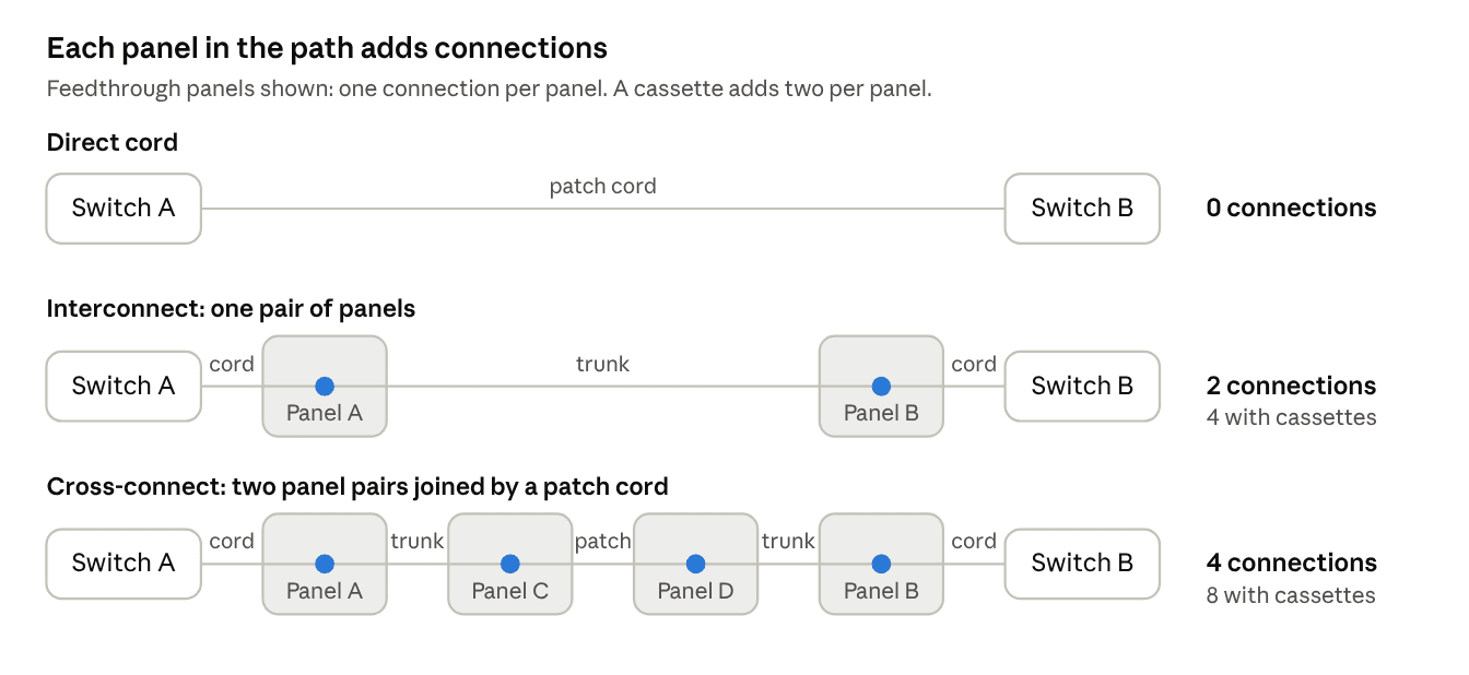
| Path | Panel type | Connections between the switches | Worst-case loss, low-loss parts: MPO 0.35 dB, LC 0.25 dB each (dB) | Worst-case loss, standard parts: MPO 0.75 dB, LC 0.50 dB each (dB) |
|---|---|---|---|---|
| Direct cord | None | 0 | 0.0 | 0.0 |
| Interconnect: each switch to its own panel, one trunk between | Feedthrough | 2 MPO | 0.7 | 1.5 |
| Interconnect | Cassette | 2 MPO + 2 LC | 1.2 | 2.5 |
| Breakout: one MPO optic to 4 or 8 LC ports | Feedthrough, then breakout cassette | 2 MPO + 1 LC per lane | 0.95 | 2.0 |
| Cross-connect: two panel pairs joined by a patch cord | Feedthrough | 4 MPO | 1.4 | 3.0 |
| Cross-connect | Cassette | 4 MPO + 4 LC | 2.4 | 5.0 |
| Out through a cross-connect and back (lab stress test) | Feedthrough | 8 MPO | 2.8 | 6.0 |
The 0.75 dB standard MPO figure is the TIA-568 maximum per mated pair. TIA allows the same for LC; 0.50 dB is typical of standard-grade LC parts. Low-loss figures are typical maximums for premium parts. A standard-grade breakout already exceeds the 1.9 dB budget of a 400G-SR8. Fiber loss is extra: up to 0.35 dB per 100 m of multimode at 850 nm, and 0.5 to 1.0 dB per km of single-mode at 1310 nm (TIA-568 maximums).
03Loss budgets, 100G to 800G
Multimode 400G and 800G optics have the least room. Two standard-grade MPO connections leave them 0.2 to 0.4 dB, and a cross-connect puts them over the limit. Values in red mean the path exceeds the optic's budget.
| Optic (reach) | Fiber, connector, polish | Loss budget (dB) | Left after 2 connections, low-loss / standard (dB) | Left after 4 connections, low-loss / standard (dB) | Left after 8 connections, low-loss / standard (dB) | Watch for |
|---|---|---|---|---|---|---|
| 800G-VR8 (50 m) | OM4, MPO-16 or 2 x MPO-12, APC | 1.7 | 1.0 / 0.2 | 0.3 / -1.3 | -1.1 / -4.3 | Smallest budget of any common optic |
| 400G-SR8 (100 m) | OM4, MPO-16, APC | 1.9 | 1.2 / 0.4 | 0.5 / -1.1 | -0.9 / -4.1 | Angled polish on multimode |
| 400G-SR4.2 and 100G-SR4 (100 m) | OM4, MPO-12, UPC | 1.9 | 1.2 / 0.4 | 0.5 / -1.1 | -0.9 / -4.1 | UPC, same budget as SR8 |
| 400G BiDi, vendor-specific (70 m) | OM4, duplex LC, UPC | 1.9 | 1.4 / 0.9 | 0.9 / -0.1 | -0.1 / -2.1 | LC optic on a tight multimode budget |
| 400G-DR4 and 800G-DR8 (500 m) | OS2, MPO-12 (DR4); 2 x MPO-12 or MPO-16 (DR8), APC | 3.0 | 2.3 / 1.5 | 1.6 / 0.0 | 0.2 / -3.0 | Reflections: each added UPC connection tightens the limits |
| 4x100G-FR (2 km) | OS2, MPO-12, APC | 4.0 | 3.3 / 2.5 | 2.6 / 1.0 | 1.2 / -2.0 | Reflections; fiber loss at 2 km |
| 4x100G-LR (10 km) | OS2, MPO-12, APC | 6.3 | 5.6 / 4.8 | 4.9 / 3.3 | 3.5 / 0.3 | Fiber loss at 10 km takes much of the budget |
| 400G-FR4 (2 km) | OS2, duplex LC, UPC | 4.0 | 3.5 / 3.0 | 3.0 / 2.0 | 2.0 / 0.0 | Reflections; fiber loss at 2 km |
| 400G-LR4 (10 km) | OS2, duplex LC, UPC | 6.3 | 5.8 / 5.3 | 5.3 / 4.3 | 4.3 / 2.3 | Fiber loss at 10 km takes much of the budget |
Connections are counted between the switches, in the optic's own connector type, for short runs. Subtract fiber loss at full length, and use the cassette totals in section 02 for MPO-to-LC paths. Budgets are the maximum channel insertion loss in published data sheets; check the data sheet for the exact optic in use.
04Seven causes of link flaps
These are the seven cabling causes behind flaps through patch panels. Each leaves a different pattern in the switch counters, which is the fastest way to tell them apart.
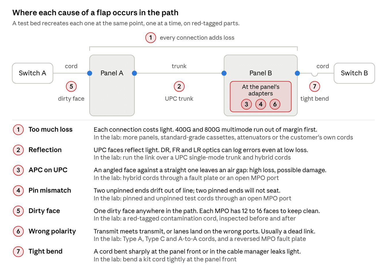
| # | Cause | What the switch shows (typical) | Most exposed optics | How to confirm |
|---|---|---|---|---|
| 1 | Too much loss | Receive power low on every lane, near the optic's minimum. Corrected FEC counts high. Flaps follow temperature changes or cord movement | 400G and 800G multimode | Measure end-to-end loss with a light source and power meter; compare with section 03 |
| 2 | Reflection | Receive power normal, but pre-FEC BER higher than the baseline. Cleaning does not help when the reflection comes from UPC polish | 100G-per-lane single-mode (DR, FR, LR) | Count the UPC connections in the path; check reflectance with a high-resolution OTDR or a return loss meter |
| 3 | APC mated to UPC | Receive power several dB low on all lanes, or no link at all. End faces may be damaged | Any optic on APC MPO | Check connector housing colors (green is APC) on both sides of each adapter; inspect the end faces with a scope |
| 4 | Pin mismatch | Unpinned to unpinned: receive power differs lane to lane and shifts when the cord is touched. Pinned to pinned: the connectors do not seat, so loss is high or there is no link | All MPO optics | Confirm one pinned and one unpinned connector at every MPO adapter |
| 5 | Dirty end face | One or a few lanes low or erroring while the rest are normal | MPO optics most often: 12 to 16 faces per connector | Inspect with a fiber scope, clean, and measure again |
| 6 | Wrong polarity or lane order | No light received and the link never comes up. On breakouts, ports come up to the wrong neighbor | MPO optics and breakouts | Trace the polarity type (A, B or C) of every cord and trunk; check neighbors with LLDP |
| 7 | Tight bend | Receive power drops when a cord is moved or dressed, and recovers when the bend is relaxed | Cords that are not bend-insensitive, multimode or single-mode | Look for kinks at the panel front and in cable managers |
Reproduce these faults in your own lab
The Wave2Wave link-flap test bed ships as a two-panel or four-panel kit, with a red-tagged fault kit for every cause above.
05Building a test bed
A test bed recreates a customer's path at the panel level, then adds one fault at a time. It needs configurations that match real paths, panels that hold every connector type, and build rules that keep the normal setups clean. Changing a test means moving patch cords at the panels; the trunks stay in place.
Configurations
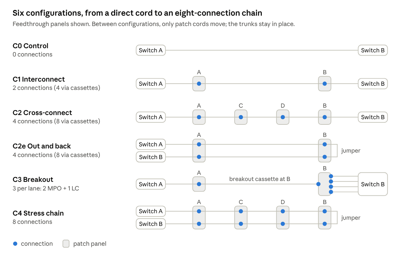
| Configuration | What it simulates | Connections, feedthrough / cassette | Panels |
|---|---|---|---|
| C0 Control | Switch cabled straight to switch. The reference for every test | 0 / 0 | 0 |
| C1 Interconnect | Each switch to its own panel, one trunk between. The most common layout | 2 / 4 | 2 |
| C2 Cross-connect | Two panel pairs joined by a patch cord, as in a main cross-connect | 4 / 8 | 4 |
| C2e Out and back | C2's connection count on two panels: out to the far panel, through a short jumper, and back | 4 / 8 | 2 |
| C3 Breakout | One 400G or 800G port split into 4 or 8 lower-speed ports on the other switch | 3 per lane: 2 MPO + 1 LC | 2 |
| C4 Stress chain | Out through the cross-connect and back, on feedthroughs. More connections than most real sites | 8 / not used | 4 |
Cable setups
Four setups on two fiber types (OM4 multimode and OS2 single-mode) give eight cable setups. MPO-MPO covers MPO-12 and MPO-16 and, on multimode, both UPC (SR4.2, SR4) and APC (SR8, VR8) versions, because these cannot be mated to each other.
| Cable setup | Optic at Switch A | Panel hardware | Optic at Switch B |
|---|---|---|---|
| MPO-MPO | MPO | MPO feedthrough in each panel | MPO |
| LC-LC | LC | LC feedthrough in each panel, one for multimode and one for single-mode | LC |
| MPO-LC (LC optics over an MPO trunk) | LC | MPO-to-LC cassette in each panel | LC |
| Breakout | MPO, 400G or 800G | MPO feedthrough at the near panel, breakout cassette at the far panel | 4 or 8 LC ports |
Panels
Every panel uses the same 2U, 12-slot enclosure, with cassettes mounted vertically. A near panel sits beside the switch that holds the optic; a far panel sits at the other end of the trunk. Each module holds one connector type, one polish and one fiber type, so slots 1 to 9 hold the same nine modules in every panel: two MPO-to-LC cassettes, three MPO-12 feedthroughs, two MPO-16 feedthroughs and two LC feedthroughs. Far panels fill slots 10 to 12 with breakout cassettes for multimode UPC, multimode APC and single-mode APC. One near panel holds the fault plates.
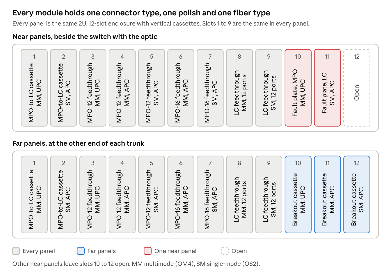
Slots 1 to 9 match on every panel, so any cable setup runs between any near and far panel. In the four-panel kit, Panels A and D are near panels and Panels B and C are far panels.
Build rules
| Rule | Specification | Why |
|---|---|---|
| MPO pins | Optics and cassettes are pinned. All MPO cords and jumpers are unpinned. Trunks are pinned at feedthrough ends and unpinned at cassette ends, marked on both ends | Two unpinned sides misalign; two pinned sides damage each other |
| Polarity | One method throughout: Type B MPO trunks and cords, key-up to key-down adapters, reversible LC cords. APC connectors only mate key-up to key-down, so the key-up to key-up fault plate takes UPC cords only | Transmit always reaches receive. Other types belong in the fault kit |
| Polish | APC on single-mode MPO and on multimode MPO for optics that require it; UPC elsewhere. Angled parts are green. Each feedthrough and cassette holds one connector type, one polish and one fiber type | Matches each optic's requirement and prevents accidental mixing |
| Part grade | Low-loss parts on the normal setups: at most 0.35 dB per MPO and 0.25 dB per LC connection | Keeps normal setups healthy, so the only change is the fault added |
| Labels and test data | Every port labeled to TIA-606 and numbered the same on both panels of a pair. Measured loss for every cable and cassette | Engineers can record the exact path and start from a known baseline |
| Fault isolation | Faults created only on dedicated fault plates and open ports, using red-tagged parts | Protects the cassettes and trunks that carry normal links |
Fault kit
| Part or method (fault parts are red-tagged) | Reproduces |
|---|---|
| Standard-grade cassettes, multimode and single-mode | 1 Too much loss on MPO-to-LC paths |
| Single-mode attenuators, LC and MPO, 1 to 7 dB | 1 Too much loss on single-mode paths; loss margin test |
| Added connections in the four-panel stress chain, or cords taken from the customer's site | 1 Too much loss on multimode MPO paths |
| UPC single-mode MPO trunk and APC-to-UPC hybrid cords, run on spare ports of the single-mode APC feedthrough | 2 Reflection |
| APC-to-UPC hybrid cords, LC and MPO | 3 APC mated to UPC |
| Pinned and unpinned MPO test cords | 4 Pin mismatch |
| Contamination test cords, MPO and LC | 5 Dirty end face |
| Type A and Type C MPO cords, LC A-to-A cords, reversed MPO fault plate | 6 Wrong polarity or lane order |
| A kit patch cord bent tightly at the panel front (no extra part) | 7 Tight bend |
06Test procedure
Run the steps in order, one optic type at a time, and take the same readings at every step so each result compares with the baseline.
| Step | Configuration | What to do | What it shows |
|---|---|---|---|
| 1 Baseline | C0 | Run each optic on a direct cord | Reference readings for each optic |
| 2 One pair of panels | C1, each cable setup | Move the cords to the panels | A clean link, with receive power lower by the path loss |
| 3 Cross-connect stress | C2 or C2e, then C4 | Run 24 hours and log room temperature | 400G and 800G multimode near or past the limit: rising errors, possible flaps |
| 4 Loss margin | C1 | Single-mode: add attenuation 1 dB at a time. Multimode: swap in the standard-grade cassette or add connections | How much extra loss each optic tolerates before it flaps |
| 5 Fault scenarios | C1 or C2e | Add one cause from section 04 at a time | How each cause shows in the readings, to match against customer cases |
| 6 Breakout check | C3 | Trace each lane to its switch port | Every lane lands on the right port |
| 7 Full reach (optional) | C1 or C2 plus a distance spool (up to 100 m multimode, 2 km single-mode) | Repeat steps 2 and 3 | The effect of full cable length on top of the connections |
| Reading to record at every step | Why it matters |
|---|---|
| Transmit and receive power, per lane | Shows the loss and which lanes are affected |
| Pre-FEC BER | The earliest warning: it rises before the link drops |
| FEC corrected and uncorrected codewords | Uncorrected codewords mean lost frames; a sustained rise usually comes just before the link drops |
| Link-flap log, with timestamps | The count and timing of drops |
| Room temperature | Links near their limit often flap as temperature changes |
07Worked example: reproducing a 400G-SR8 flap
A customer reports a 400G-SR8 link that flaps after it was moved onto a cross-connect. The team runs the same pair of optics through more and more connections, following steps 1 to 3 of the test procedure.
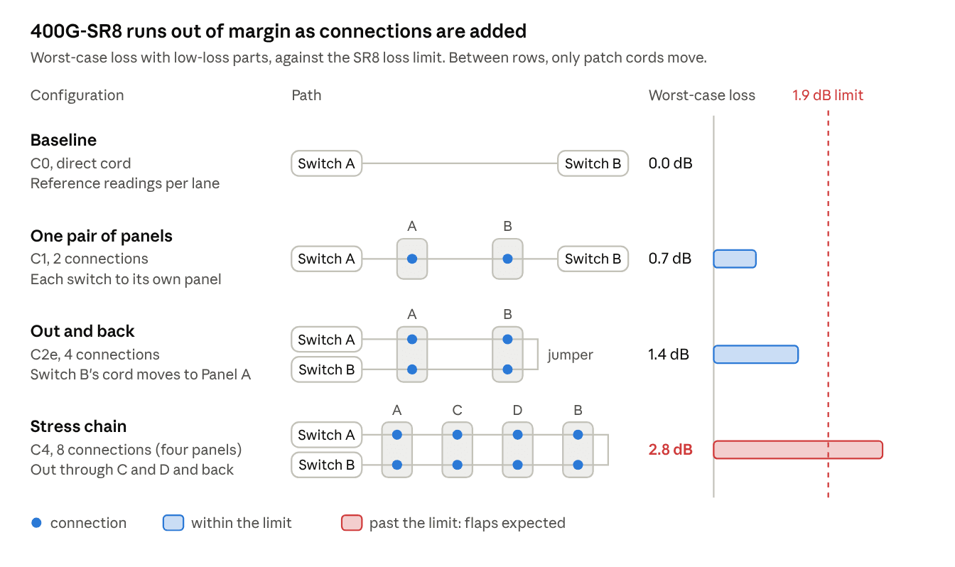
| Configuration | Connections | Worst-case loss, low-loss parts (dB) | Worst-case loss, standard parts (dB) | Expected result |
|---|---|---|---|---|
| C0 Baseline | 0 | 0.0 | 0.0 | Clean link; reference readings |
| C1 One pair of panels | 2 MPO | 0.7 | 1.5 | Clean link |
| C2e Out and back | 4 MPO | 1.4 | 3.0 | Clean on low-loss parts; over the 1.9 dB limit on standard parts |
| C4 Stress chain | 8 MPO | 2.8 | 6.0 | Over the limit: rising errors and flaps |
A customer site built with standard-grade parts goes past the limit at four connections, where the test bed's low-loss parts still pass. Once the loss pattern is recorded, the team repeats the out-and-back path with one fault from the kit at a time and compares each result with the customer's readings. The stress chain needs the four-panel kit. On two panels, low-loss parts keep SR8 within its limit, so the team adds cords taken from the customer's site to reproduce the customer's loss.
08The Wave2Wave link-flap test bed
Wave2Wave builds this test bed as a kit, in a two-panel and a four-panel version. Every part is built to the rules in section 05 and ships with its measured loss.
| Feature | Two-panel kit | Four-panel kit |
|---|---|---|
| Panels | Two 2U, 12-slot panels: one near, one far | Four 2U, 12-slot panels: two near, two far |
| Rack space | 4U | 8U, across three racks |
| Configurations | C0, C1, C2e and C3 | All six, C0 to C4 |
| Cable setups | All eight: MPO-MPO, LC-LC, MPO-LC and breakout, each on OM4 and OS2 | All eight |
| Links at once | One | Two, so a healthy link can run beside a faulty one |
| Fault kit | Included | Included |
| Test data | Measured loss on every cable and cassette, plus reflectance on single-mode | Same |
| Labels | TIA-606 port labels and a port map | Same |
| Best for | Reproducing interconnect faults and loss on one panel pair | Adding true cross-connects and stress testing |
| Price | Request a quote | Request a quote |
Open slots in the near panels leave room for newer connector types. Cables ship packed separately from the panels and connect on site using the labeled port map.
Talk to our engineers
Tell us which optics and cabling your customers run, and we will size the kit. info@wave2wave.io or +1 (866) 473-2701.
Bill of materials
Quantities for each kit. Part numbers and pricing come with the quote. The short jumpers and the fault kit are one set in either kit.
| Line | Part | Two-panel kit | Four-panel kit |
|---|---|---|---|
| Panel hardware | |||
| PH1 | 2U 12-slot enclosure, all panels | 2 | 4 |
| PH2 | MPO-to-LC cassette, MPO-12 UPC to 6 x LC duplex, OM4 | 2 | 4 |
| PH3 | MPO-to-LC cassette, MPO-12 APC to 6 x LC duplex, OS2 | 2 | 4 |
| PH4 | MPO-12 feedthrough, OM4, UPC, 12 ports, key up to key down | 2 | 4 |
| PH5 | MPO-12 feedthrough, OM4, APC, 12 ports, key up to key down, green | 2 | 4 |
| PH6 | MPO-12 feedthrough, OS2, APC, 12 ports, key up to key down, green | 2 | 4 |
| PH7 | MPO-16 feedthrough, OM4, APC, 6 ports, key up to key down, green | 2 | 4 |
| PH8 | MPO-16 feedthrough, OS2, APC, 6 ports, key up to key down, green | 2 | 4 |
| PH9 | LC feedthrough (adapter plate), 12 ports OM4 (aqua) | 2 | 4 |
| PH10 | LC feedthrough (adapter plate), 12 ports OS2 (blue) | 2 | 4 |
| PH11 | Breakout cassette, 2 x MPO-12 UPC (8 fiber) to 8 x LC duplex, OM4, far panels | 1 | 2 |
| PH12 | Breakout cassette, 2 x MPO-12 APC (8 fiber) to 8 x LC duplex, OM4, far panels | 1 | 2 |
| PH13 | Breakout cassette, 2 x MPO-12 APC (8 fiber) to 8 x LC duplex, OS2, far panels | 1 | 2 |
| Trunks, 5 m (MPO trunks are Type B) | |||
| TR1 | MPO-12 UPC F-F, OM4, 12F, cassette to cassette | 1 | 2 |
| TR2 | MPO-12 APC F-F, OS2, 12F, cassette to cassette | 1 | 2 |
| TR3 | MPO-12 UPC M-M, OM4, 12F, feedthrough | 2 | 4 |
| TR4 | MPO-12 UPC M-M, OS2, 12F, reflection test (red-tagged, uses spare ports on the OS2 APC MPO-12 feedthrough) | 1 | 2 |
| TR5 | MPO-12 APC M-M, OS2, 12F, feedthrough | 2 | 4 |
| TR6 | MPO-12 APC M-M, OM4, 12F, feedthrough | 2 | 4 |
| TR7 | MPO-16 APC M-M, OM4, feedthrough | 2 | 4 |
| TR8 | MPO-16 APC M-M, OS2, feedthrough | 2 | 4 |
| TR9 | MPO-12 UPC M-F, OM4, 8F, feedthrough to breakout cassette | 2 | 4 |
| TR10 | MPO-12 APC M-F, OS2, 8F, feedthrough to breakout cassette | 2 | 4 |
| TR11 | MPO-12 APC M-F, OM4, 8F, feedthrough to breakout cassette | 2 | 4 |
| TR12 | LC to LC trunk, OM4, 12F | 1 | 2 |
| TR13 | LC to LC trunk, OS2, 12F | 1 | 2 |
| Patch cords, 2 m (MPO cords are unpinned, Type B) | |||
| CD1 | LC duplex uniboot, reversible, OM4 | 16 | 24 |
| CD2 | LC duplex uniboot, reversible, OS2 | 16 | 24 |
| CD3 | MPO-12 UPC, OM4 | 2 | 3 |
| CD4 | MPO-12 APC, OM4 | 4 | 6 |
| CD5 | MPO-16 APC, OM4 | 2 | 3 |
| CD6 | MPO-12 APC, OS2 | 4 | 6 |
| CD7 | MPO-16 APC, OS2 | 2 | 3 |
| Breakout harnesses and conversion cords | |||
| BH1 | Harness, MPO-16 APC to 8 x LC duplex, OM4, 2 m, for breakout of MPO-16 multimode optics such as 400G-SR8 | 1 | 2 |
| BH2 | Harness, MPO-12 APC (8F) to 4 x LC duplex, OM4, 2 m, for breakout of 8-fiber APC multimode optics | 2 | 4 |
| BH3 | Conversion cord, MPO-16 APC to 2 x MPO-12 APC (8F), OS2, 1 m, connects MPO-16 single-mode optics to the breakout cassette | 1 | 2 |
| Short jumpers, 0.5 m, for out-and-back tests | |||
| JP1 | LC duplex, OM4 | 4 | 4 |
| JP2 | LC duplex, OS2 | 4 | 4 |
| JP3 | MPO-12 UPC, OM4 | 2 | 2 |
| JP4 | MPO-12 APC, OS2 | 2 | 2 |
| JP5 | MPO-16 APC, OM4 | 1 | 1 |
| JP6 | MPO-16 APC, OS2 | 1 | 1 |
| Fault-injection kit, red-tagged | |||
| FK1 | Fault plate, MPO-12, OM4, UPC, key up to key up, 6 ports (near panel, slot 10) | 1 | 1 |
| FK2 | Fault plate, LC APC duplex, OS2, 12 ports, green (near panel, slot 11) | 1 | 1 |
| FK3 | Standard-grade cassette, MPO-12 UPC to 6 x LC, OM4 | 2 | 2 |
| FK4 | Standard-grade cassette, MPO-12 APC to 6 x LC, OS2 | 2 | 2 |
| FK5 | LC UPC attenuator, single-mode: 1, 2, 3, 5, 7 dB, 2 each | 10 | 10 |
| FK6 | MPO-12 APC in-line attenuator, single-mode: 1 dB and 3 dB | 2 | 2 |
| FK7 | LC APC to LC UPC hybrid duplex cord, OS2, 2 m | 2 | 2 |
| FK8 | MPO-12 APC to MPO-12 UPC hybrid cord, OS2, 2 m | 2 | 2 |
| FK9 | MPO-12 Type A cord, 2 m (1 OM4 UPC, 1 OS2 APC) | 2 | 2 |
| FK10 | MPO-12 Type C cord, 2 m (1 OM4 UPC, 1 OS2 APC) | 2 | 2 |
| FK11 | LC duplex A-to-A cord, 2 m (2 OM4, 2 OS2) | 4 | 4 |
| FK12 | MPO-12 pinned-to-unpinned cord, 2 m (1 OM4 UPC, 1 OS2 APC) | 2 | 2 |
| FK13 | Contamination test cords, red-tagged, 2 m: 2 MPO-12 and 2 LC (set) | 1 | 1 |
Optional distance kit
Fiber spools for full-reach tests. Each spool works with either kit.
| Line | Part | Qty |
|---|---|---|
| DK1 | Distance spool, OM4, MPO-12 UPC, 100 m | 1 |
| DK2 | Distance spool, OM4, MPO-12 APC, 50 m | 1 |
| DK3 | Distance spool, OM4, MPO-16 APC, 100 m | 1 |
| DK4 | Distance spool, OS2, MPO-12 APC, 500 m | 1 |
| DK5 | Distance spool, OS2, LC UPC duplex, 2 km | 1 |
09Frequently asked questions
What causes link flapping after a link is cabled through a patch panel?
Usually the cabling: too much loss for the optic's budget, reflections at UPC connections on single-mode, an APC connector mated to a UPC connector, an MPO pin mismatch, a dirty end face, wrong polarity, or a tight bend. At 400G and 800G, check total loss first.
How many patch panel connections can a 400G-SR8 link tolerate?
A 400G-SR8 allows 1.9 dB of channel loss. Two low-loss MPO connections use up to 0.7 dB and two standard-grade connections up to 1.5 dB. A four-connection cross-connect fits with low-loss parts (1.4 dB) but not with standard-grade parts (3.0 dB).
Do 400G and 800G optics need APC connectors?
Many do. In published data sheets, 400G-SR8, 400G-DR4, 800G-VR8 and 800G-DR8 require angled (APC) MPO connectors, while 400G-SR4.2 and LC optics such as 400G-FR4 use UPC. Check the data sheet for the exact optic in use.
What is the difference between a feedthrough and a cassette?
A feedthrough is a panel plate of plain adapters, so it adds one connection per panel. A cassette converts an MPO trunk to LC ports and adds two connections per panel, so it uses more of the loss budget.
Sources
- Cisco OSFP 800G Transceiver Modules Data Sheet: loss budgets and APC requirements for 800G-VR8 and 800G-DR8
- Cisco 400G QSFP-DD Cable and Transceiver Modules Data Sheet: loss budgets and connector polish for 400G-SR8, SR4.2, BiDi, DR4, 2x100G-SR4, 4x100G-FR and LR, FR4 and LR4
- IEEE P802.3cd, channel insertion loss vs. discrete reflectances (Dawe, July 2017): how reflective connections lower the allowed loss for 100GBASE-DR
- Fiber Optic Association: TIA-568 fiber optic requirements: 0.75 dB maximum per mated connector pair; 3.5 dB/km multimode attenuation at 850 nm; 0.5 to 1.0 dB/km single-mode at 1310 nm
- Fluke Networks: Getting 12- and 8-fiber MPO polarity right: APC MPO connectors must mate key-up to key-down
Technical reference
Link flap troubleshooting through patch panels and structured cabling. Channel insertion loss budgets: 800G-VR8 1.7 dB (OM4, 50 m, MPO APC); 400G-SR8 1.9 dB (OM4, 100 m, MPO-16 APC); 400G-SR4.2 and 100G-SR4 1.9 dB (OM4, 100 m, MPO-12 UPC); 400G-DR4 and 800G-DR8 3.0 dB (OS2, 500 m, MPO APC); 4x100G-FR and 400G-FR4 4.0 dB (2 km); 4x100G-LR and 400G-LR4 6.3 dB (10 km). Connection loss: TIA-568 maximum 0.75 dB per mated pair; low-loss MPO 0.35 dB, low-loss LC 0.25 dB. Feedthrough adds 1 connection per panel; MPO-to-LC cassette adds 2. Interconnect, cross-connect and breakout connection counts. MPO polarity Type A, Type B, Type C; key-up to key-down adapters; pinned and unpinned (male and female) MPO. APC vs UPC polish; reflectance and multipath interference on 100G-per-lane PAM4 single-mode (100GBASE-DR, 400GBASE-DR4, FR4, LR4). Pre-FEC BER, FEC corrected and uncorrected codewords, receive power per lane. Fault injection: attenuators, hybrid cords, contamination, tight bends, pin mismatch, reversed polarity.
Related articles.
Need a link-flap test bed for your lab?
Tell us which optics and cabling your customers run, and we will size the kit.